- 您现在的位置:买卖IC网 > Sheet目录625 > LC4HW-R6-DC24VS (Panasonic Electric Works)COUNTER DIGITAL 24VDC SCREW TERM
�� �
�
�PRECAUTIONS IN USING THE LC4H SERIES�
�Precautions� during� usage�
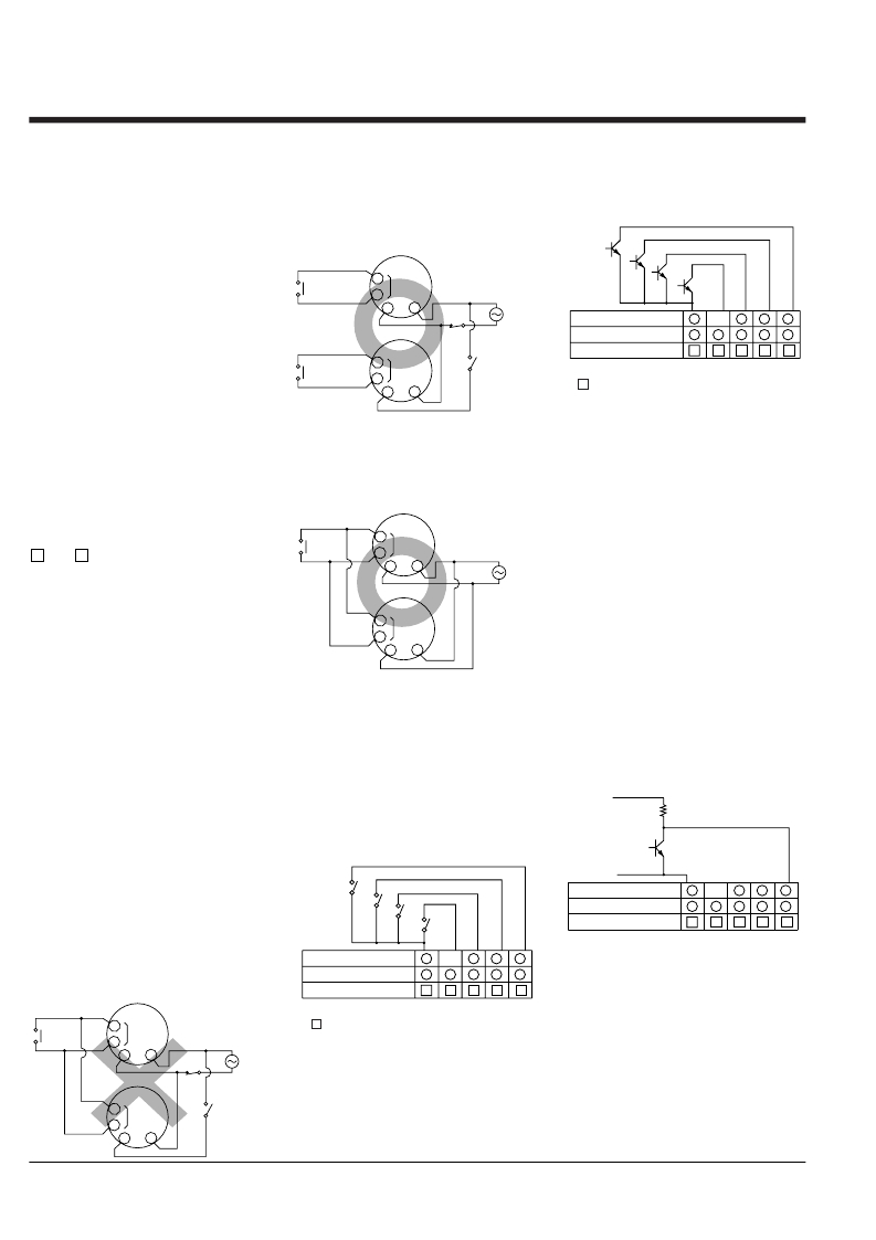
�1.� Terminal� wiring�
�1)� When� wiring� the� terminals,� refer� to� the�
�terminal� layout� and� wiring� diagrams� and�
�be� sure� to� perform� the� wiring� properly�
�without� errors.�
�2)� When� using� the� instrument� with� an�
�If� independent� power� circuitry� must� be�
�used,� keep� the� input� contacts� or� transis-�
�tors� separate� from� each� other,� as� shown�
�in� Fig.� B.�
�(Fig.� B)�
�Input� contact�
�Also,� use� transistors� with� a� residual� volt-�
�age� of� less� than� 2� V� when� the� transistor�
�is� on.�
�Reset� input�
�Input� 1�
�flush� mounting,� the� screw-down� terminal�
�type� is� recommended.� For� the� pin� type,�
�use� either� the� rear� terminal� block�
�or� transistor�
�3�
�Input�
�terminal�
�Input� 2�
�Lock�
�input�
�(AT78041)� or� the� 8P� cap� (AD8-RC)� for�
�the� 8-pin� type,� and� the� rear� terminal�
�block� (AT78051)� or� the� 11P� cap� (AT8-�
�DP11)� for� the� 11-pin� type.� Avoid� solder-�
�ing� directly� to� the� round� pins� on� the� unit.�
�When� using� the� instrument� with� a� front�
�Input� contact�
�or� transistor�
�3�
�2�
�2�
�10�
�Input�
�terminal�
�10�
�Power�
�supply�
�8-pin� type� 1� —� 5� 4�
�11-pin� type� 3� 4� 5� 6�
�Screw� terminal� type� 6� 7� 8� 9�
�Note:� The� LC4H-W� does� not� have� the� lock� input�
�R� ,� 7� .�
�3�
�7�
�10�
�panel� installation,� use� the� DIN� rail� termi-�
�*� The� short-circuit� impedance� should� be�
�nal� block� (AT8-DF8K)� for� the� 8-pin� type�
�and� the� DIN� rail� terminal� block� (AT8-�
�DF11K)� for� the� 11-pin� type.�
�3)� After� turning� the� counter� off,� make�
�sure� that� any� resulting� induced� voltage�
�or� residual� voltage� is� not� applied� to�
�power� supply� terminals� W� through� U� (8-�
�When� power� circuitry� is� not� independent,�
�one� input� signal� can� be� fed� to� two� or�
�more� counters� at� once,� as� shown� in� Fig.�
�C.�
�(Fig.� C)�
�Input� contact�
�or� transistor�
�less� than� 1� k� ?� .�
�[When� the� impedance� is� 0� ?� ,� the� current�
�coming� from� the� input� 1� and� input� 2� ter-�
�minals� is� approximately� 12� mA,� and� from�
�the� reset� input� and� lock� input� terminals� is�
�approximately� 1.5� mA.]�
�pin� type),� W� through� P� (11-pin� type)� or�
�1� and� 2� (screw� terminal� type).� (If� the�
�power� supply� wire� is� wired� parallel� to� the�
�high� voltage� wire� or� power� wire,� an�
�3�
�2�
�Input�
�terminal�
�10�
�Power�
�supply�
�Also,� the� open-circuit� impedance� should�
�be� more� than� 100� k� ?� .�
�induced� voltage� may� be� generated�
�*� As� shown� in� the� diagram� below,� from� a�
�between� the� power� supply� terminals.)�
�Input�
�non-contact� point� circuit� (proximity�
�4)� Have� the� power� supply� voltage� pass�
�through� a� switch� or� relay� so� that� it� is�
�applied� at� one� time.� If� the� power� supply�
�3�
�2�
�terminal�
�10�
�switches,� photoelectric� switches,� etc.)�
�with� a� power� supply� voltage� of� between�
�12� and� 40� V,� the� signal� can� be� input�
�is� applied� gradually,� the� counting� may�
�malfunction� regardless� of� the� settings,�
�the� power� supply� reset� may� not� function,�
�or� other� such� unpredictable� occurrence�
�may� result.�
�2.� Input� connections� (except� LC4H-�
�S/AC� type)�
�The� power� circuit� has� no� transformer�
�without� a� transformer� (power� and� input�
�terminals� are� not� insulated).� When� an�
�input� signal� is� fed� to� two� or� more� coun-�
�ters� at� once,� do� not� arrange� the� power�
�3.� Input� and� output�
�1)� Signal� input� type�
�(1)� Contact� point� input�
�Use� highly� reliable� metal� plated� contacts.�
�Since� the� contact� point’s� bounce� time�
�leads� directly� to� error� in� the� count� value,�
�use� contacts� with� as� short� a� bounce� time�
�as� possible.� In� general,� select� Input� 1�
�and� Input� 2� to� have� a� maximum� counting�
�speed� of� 30� Hz� and� to� be� reset� with� a�
�minimum� input� signal� width� of� 20� ms.�
�without� using� an� open� collector� transis-�
�tor.� In� the� case� of� the� diagram� below,�
�when� the� non-contact� point� transistor� Q�
�switches� from� off� to� on� (when� the� signal�
�voltage� goes� from� high� to� low),� the� sig-�
�nal� is� input.�
�12� to� 40V� DC�
�Reset� input�
�Q�
�circuit� in� an� independent� way.�
�If� the� counter� is� powered� on� and� off� inde-�
�pendently� as� shown� in� Fig.� A,� the� coun-�
�ter's� internal� circuitry� may� get� dam-�
�Reset� input�
�Input� 1�
�Input� 2�
�Lock�
�input�
�8-pin� type�
�11-pin� type�
�Screw� terminal� type�
�1�
�3�
�6�
�—�
�4�
�7�
�5�
�5�
�8�
�4�
�6�
�9�
�3�
�7�
�10�
�aged.Be� careful� never� to� allow� such� cir-�
�(The� above� example� is� for� reset� input)�
�cuitry.� (Figs.� A,� B� and� C� show� the� circuit-�
�ry� for� the� 11-pin� type.)�
�(Fig.� A)�
�8-pin� type�
�11-pin� type�
�Screw� terminal� type�
�1�
�3�
�6�
�—�
�4�
�7�
�5�
�5�
�8�
�4�
�6�
�9�
�3�
�7�
�10�
�2)� The� input� mode� and� output� mode�
�change� depending� on� the� DIP� switch� set-�
�Input� contact� or� transistor�
�3�
�2�
�Input�
�terminal�
�10�
�Power�
�supply�
�Note:� The� LC4H-W� does� not� have� the� lock� input�
�R� ,� 7� .�
�(2)� Non-contact� point� input�
�Connect� with� an� open� collector.� Use�
�transistors� whose� characteristics� satisfy�
�tings.� Therefore,� before� making� any� con-�
�nections,� be� sure� to� confirm� the� opera-�
�tion� mode� and� operation� conditions� cur-�
�rently� set.�
�the� criteria� given� below.�
�3�
�2�
�Input�
�terminal�
�10�
�V� CEO� =� 20� V� min.�
�I� C� =� 20� mA� min.�
�I� CBO� =� 6μA� max.�
�140�
�发布紧急采购,3分钟左右您将得到回复。
相关PDF资料
LCS-10
LIQUID LEVEL CONTROL
LD4006P0
COUNTER 6 DIGIT DUAL 4.0" RED
LD412460
DIODE MOD ISO DUAL 2400V 600A
LIRT220A
CONTROL RELAY CURRENT 220VAC
LNXC2000
COUNTER DUAL PRESET 115VAC
LP-56-850
XFRMR 115/230V 28V 1.7A 48VA PCB
LS412460
DIODE MOD ISO SGL 2400V 600A
M4L-3-10
XFRMR 115V 8.7A 1000VA
相关代理商/技术参数
LC4HWT6AC24V
制造商:OMRON 功能描述:*
LC4-MFD
制造商:Bosch Sensortec 功能描述:Metal Fire Dome for LC4 Series Loudspeakers
LC-4-S Black
制造商:Mac8 功能描述:
LC-4-S Blue
制造商:Mac8 功能描述:
LC-4-S Yellow
制造商:Mac8 功能描述:
LC4-UC06E
制造商:Bosch Sensortec 功能描述:Premium ceiling wide angle loudspeaker, 6 watt, EVAC compliant
LC-5
功能描述:打印机 LS3E, Component Label, Adhesive Vinyl Cl RoHS:否 制造商:Seiko Instruments 产品:Printer 电源电压: 每行点数:9 x 320 打印速度:52.5 cps, 80 cps 纸张宽度:112 mm
LC-5.0
功能描述:LED 光导管 Light Pipe Flex 4mm Round Lens RoHS:否 制造商:Bivar 产品:Light Pipes 颜色:Clear LED 大小: 主体形状:Cylindrical 主体长度:0.125 in 材料:Polycarbonate